Constructing large physical models is a complex undertaking
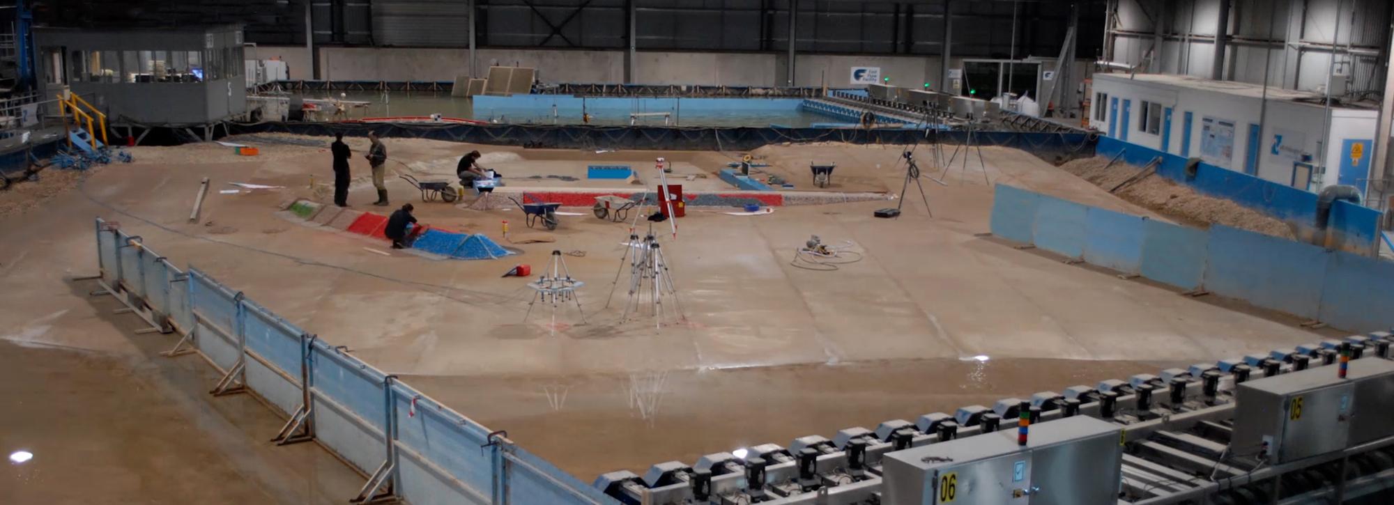
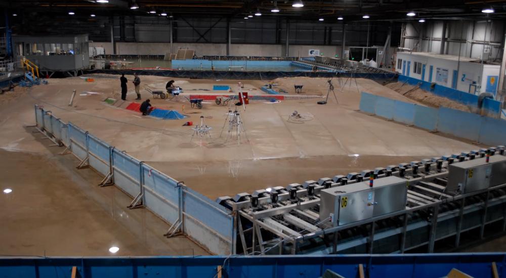
When you step inside our vast physical modelling laboratories, you could be forgiven for believing you have stepped into an aircraft hangar. World-leading science and engineering is conducted here on a huge scale, using large, complex physical models. Laboratory Manager Dr David Todd explains how such models are designed and built.
We use up to 50m3 of concrete to mould a seabed in one of our basins, and it takes over 4 tonnes of rock to construct a 20m model breakwater (at a scale of 1:60). These are typical of the enormous amounts of material that we need to build physical models, along with diggers, dumpers and fork lift trucks, a dedicated team of exceptional technicians and engineers, and a correspondingly vast space to put them in.
Our 14,000m2 modelling halls have been specifically designed to accommodate a range of huge models. With seven wave basins, five flumes, as well as an extensive custom-built facilities area, we have the largest and most versatile physical modelling facilities in Europe. We frequently run different phases of projects simultaneously, or combine basins for particularly large projects. For instance, we combined three of our wave basins to fit in a 75m model to study the Corsican coastline near Bastia Port and developments at the Port of San Antonio in Chile.
The team regularly models coastal structures and beaches in the hall, with our huge wavemakers generating waves that crash against breakwaters, or ships, or break and run back down beaches. Our flumes are used for projects such as testing fish pass models, breakwater sections, offshore wind foundations, or coastal defences, and our new state-of-the-art erosion rig can test seabed sediment samples taken from offshore, for example for new offshore wind turbine developments.
So how do these models work, and how are they designed and built?
Model design
For typical basin or flume studies, physical models involve an intensive design process, which begins with a detailed evaluation of the setting: the structure geometry and characteristics, wave climate, flow speeds and directions, bathymetry (the shape of the seabed), surrounding coastline, and sediment characteristics. Design criteria are evaluated by our expert scientists, engineers and technicians to determine the most appropriate scale, setting and orientation for the model.
The requirements of the model, alongside facility availability, determine which facility the model will occupy. The model layout within the facility is then drawn up by the in-house CAD team. Based upon the complexity of the sea bed, lines are extracted at 1, 2, or 3m intervals through the bathymetry, with these “guide lines” – known as “bars” – forming the basis of construction within the facility. For particularly complex regions, sub-metre drawings are produced.
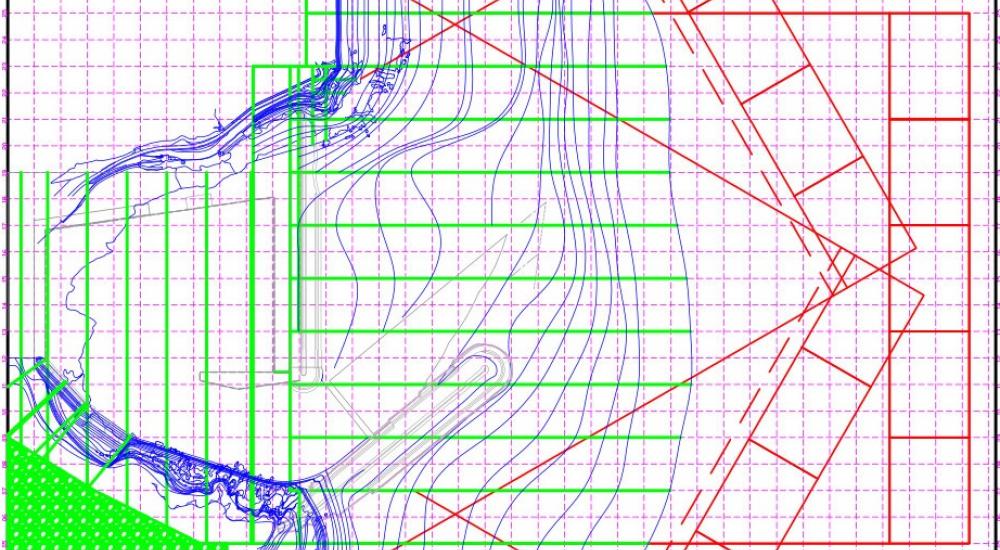
In this drawing, green represents the bars. These are the straight line sections that are installed as wooden templates or concrete bars. Red represents the wave paddles and wave guides. There are three different sets as for this particular model waves were tested from three different directions. The wave guides are used to ensure that the waves develop correctly and do not begin to spread out away from the area of interest.Blue represents the bathymetric contours. This is the shape of the seabed and surrounding area (cliffs etc.) that the model is representing. Grey represents the structures (e.g. breakwaters and quays) that are being tested.
Model construction
The heights along the bars are extracted, and wooden templates are made in the workshops that follow the heights along the lines. A coordinate system is set up in the basin, and the templates are installed using highly accurate measuring equipment (including laser levels and cross-line lasers) to ensure accurate placement.
Model construction in images
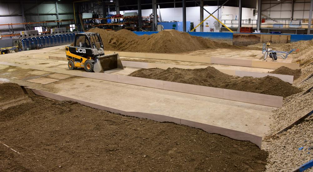
Wooden template bars with spacing of 3m on location in a model, with ballast filling in between templates.
Screeding a 3m bay. Concrete is poured and the screeding bar (striker) pulled over the top to ensure a smooth, accurate surface between the bars.
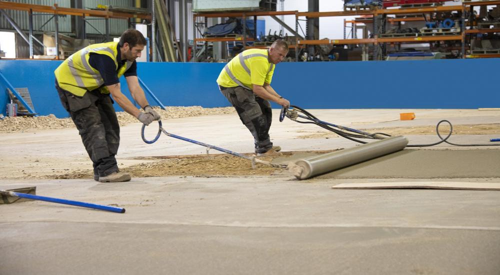
Ballast material (a sand/gravel/crushed concrete mix) is installed and compacted between the bars, to a height of 50mm from the top. In regions where the bathymetry is too deep for wooden bars to be stable, the ballast material is put in and levelled first, and concrete bars – strips of concrete that are laser levelled in to the correct height – are moulded on top. The final 50mm, up to the top of the wooden or concrete bars, is then concreted over using a roller striker [Image 3], where possible.
In particularly complex or steep areas, concreting is completed by hand, to ensure an accurate finish. While this sounds like a simple process, large models may require in excess of 200 metres of bars, 600 tonnes of ballast material and 50m3 of concrete to form the bathymetry.
In parallel with the bathymetry construction, the structures to be tested may be under construction in the in-house workshops, the rock to be used in breakwater construction is being prepared using an automated weighing system, while our technicians prepare the data logging systems and instrumentation required – typically wave probes, pressure transducers, load cells, strain gauges, laser scanners, video and photo cameras.
Following completion of the bathymetry construction, the wavemakers are moved into position, instrumentation is installed, and any structures required during the model calibration phase are positioned. Our typical construction tolerances are within +/-2mm, so that if you stood on one of our physical models, at a typical scale of 1:50 (though many of our models operate at much larger scales due to the sizes of our facilities) you would with be within 0.1m of the actual location at full scale.
Other types of models – including pumping stations or drop shafts – follow a similar design procedure, but may be entirely constructed by the workshops team from timber, foam and Perspex, and built in our extensive custom-build facilities area. Pumps, pipework and instrumentation are prepared by our technicians and installed on the model.
With over 70 years’ experience of scaling, designing and constructing physical models, we are world-leaders in this field. With expert engineers, scientists and technicians taking care of every aspect from model design, through construction, instrumentation, calibration and testing, we produce highly accurate physical models, leading to both reduced risks, and reduced costs, for our suite of world-wide clients.
The building of a hydraulic scaled model for the Aberdeen Harbour expansion,
If you’d like to know more, you can also watch our video on YouTube showing the building of a hydraulic scaled model for the Aberdeen Harbour expansion, and some of the tests series performed to assess the design.