Erosion rate measurement
Upfront testing keeps wind farms spinning
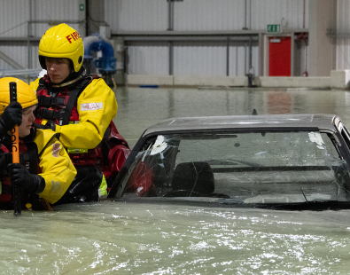
For fixed bottom wind turbines to operate safely and at optimum efficiency, producing maximum electricity, they need to remain secure and stable in moving waters.
A wind turbine risks becoming unstable if the seabed erodes around its foundations, which can occur over time by currents and waves flowing around the structure. The amount of erosion is dependent upon the speed of the water, the type of sediment, and the size of the structure that’s above the seabed.
Fortunately, we can design engineering solutions to overcome this erosion, a process known as scour. As part of forecasting the scour around a structure and designing protection for it, samples of sediment from that seabed need to be collected and analysed. This analysis should include a study of how that sediment will erode over a number of years.
Erosion testing of marine soils in the laboratory is generally considered to be the most reliable approach to assessing field performance – as per windfarm guidance DNV-GL-ST-0126, Support structures for wind turbines, para 7.3.1.6.
Site survey data alone is not sufficient as this will only take into account surface conditions at the time of the survey. Erosion testing of sediment core samples from across a site allows us see below the surface and analyse the erodibility of the different layers of sediments. The data can be used to predict levels of erosion across a site over time and quantify scour risk.
Technical specifications
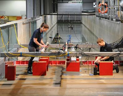
In our laboratories in Oxfordshire, UK, we have two erosion rigs. Both facilities can test sediment core samples retrieved from site locations. Our modified EFA will take 3” or 3.5” OD core liners and can generate flow speeds up to 7.0 m/s to erode granular and stiffer soils. Our own design rig requires project specific setup and can take cores up to 110 mm OD with flow speeds up to 2.0 m/s.
Technical specification
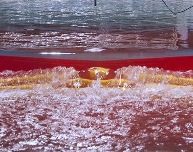
Our erosion function apparatus (EFA) rig has been customised to include adapters so that we have the ability to use both larger 3.5” diameter core tubes (89 mm outside diameter (OD) and 82.5 mm inside diameter) and 3” (76.2 mm OD) Shelby tubes. The EFA can generate flow speeds up to 7.0 m/s to erode stiffer cohesive soils and also includes a manual valve for low flow control to erode softer or granular soils.
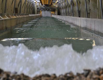
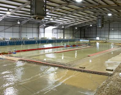
Our erosion rig has a central testing duct, 400 mm wide, 100 mm deep and 3000 mm long, and can generate flow velocities of up to 2.0 m/s. Core samples are mounted under the central testing section of the duct in their natural orientation and as the top part of the core exposed to the current is eroded, the remaining core sample is extruded up through the sample tube using a hand wound crank and piston plate. The erosion rig will take core samples up to 110 mm in diameter (OD).
For more information
Richard Whitehouse